Gear / Bearing Support
The bearing support uses the the spring loaded locking
pin with the ball handle
to "lock" the shaft for attaching and removing the worm
gear blank.
The bearing support uses the the spring loaded locking
pin with the ball handle
to "lock" the shaft for attaching and removing the worm
gear blank.
The bearing support in my
opinion is the most important part of the hobbing process. The gear blank
needs
to be perfectly centered and set at the proper
cutting height to produce an accurate worm gear. You also have
to make sure that there is no flexing or movement
of the gear blank while hobbing.
Since I plan on building more worm gears I
decided to go to the extra effort to build a bearing support that I
can use over and over without having to spend
a ot of time setting up. Here's what I came up with and it works
beautifully. I didn't include many measurements
since every lathe is a little different.
Hopefully the pictures will give you some
ideas.
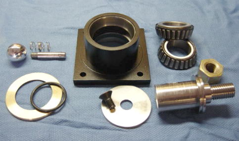
Here's all the pieces laid out. I built this entirely from materials
I had on hand.
The bearings I used are tapered wheel bearings ( trailer wheel bearings
)
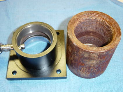
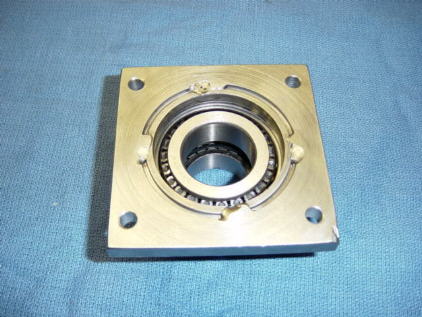
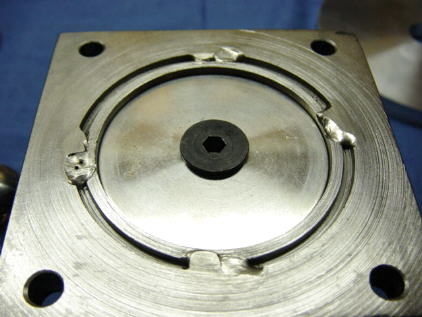
Bottom view with bearing in place. After the 4 welds were made
I faced the bottom of the mount to achieve a flat surface.
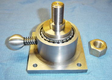
The shaft was turned from 1 7/8" OD stainless steel.
The attaching threads are 3/4"-10 tpi and were turned on
the 9x lathe. The ball handle on the
left is a spring loaded
pin that when pushed will "lock up" the shaft to allow the
attaching nut to be tightened or loosened.
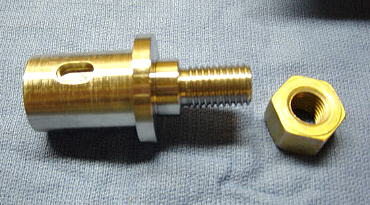
The finished shaft. Two slots were milled in the side of the shaft
to allow
for a locking pin to fit into. The milling was done on my Grizzly mini
mill.
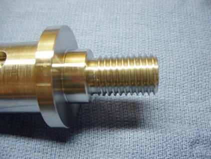
The threads were cut to 3/4"-10 , the shoulder next to the threads
is a precise 1" OD for easy centering the worm blank.
The threads were done on the 9x20.
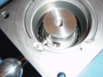
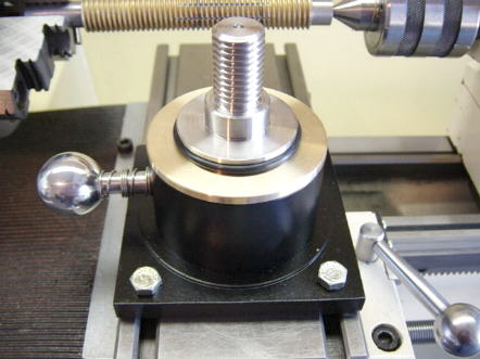
This shows how the spring loaded locking pin works.
This allows the attaching nut to be tightened and loosened
without the shaft turning.
The bottom of the shaft was drilled and tapped to a 3/8"-16 thread.
The shaft length is approx 1/16" shorter than the bearing.
This allows a large washer and screw ( shown in the next pic )
to tighten the shaft and bearings.
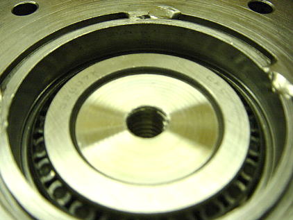
A large steel washer and a beveled 3/8"-16 allen head screw provide
the bearing pre load adjustment. Locktite was applied to the threads
for final assembly. The large washer has just enough clearance to turn
inside the bearing housing.
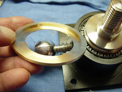
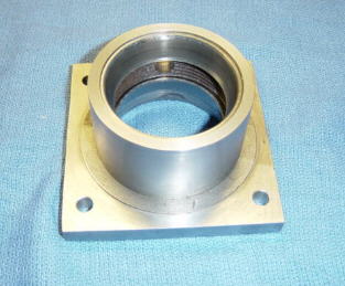
A thin brass ring works as a cover to protect the top bearing from
any cuttings.
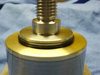
I turned a groove to allow a rubber "O" ring. The rubber "O" ring
holds the brass cover in place.
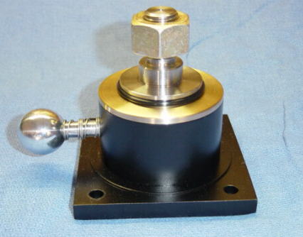
Finished Bearing Support !
Click below for more details
| Bearing Support Building Pics | Gear Blank Building Pics | Worm / Cutter
Building Pics |
Hobbing
a Gear & Comments |
9 x 20 Lathe Page | 9 x 20 Projects Page | Home |
Comments / Questions / Suggestions or Add Your Link
This information is provided for personal use only
Copyright 2001 / 2003 Steve
Bedair