Meister BC-10L DRO
Mounting "X" Axis Scale
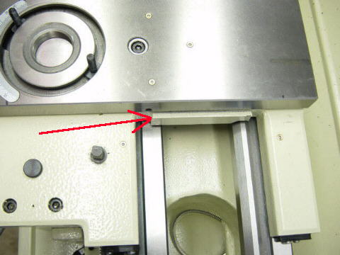
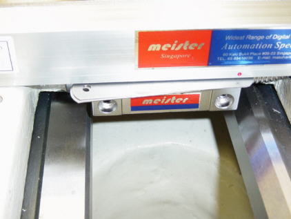
I chose to attach the "X" axis glass scale to the
rear of the compound slide and saddle. This area will be clear
of chips and oil. One problem shown above with the red arrow is that the saddle area protruded out from the
cross slide causing the scale to cover the oil ports on the saddle.
of chips and oil. One problem shown above with the red arrow is that the saddle area protruded out from the
cross slide causing the scale to cover the oil ports on the saddle.
Note: You do not have to be
concerned on which direction the reading head moves. The direction can be
changed easily for either axis from the control panel.
changed easily for either axis from the control panel.
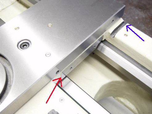
This shows the saddle after milling. It will allow the scale to be mounted flush against the compound slide.
I also milled a slot for the reader cable to pass through shown with a blue arrow.
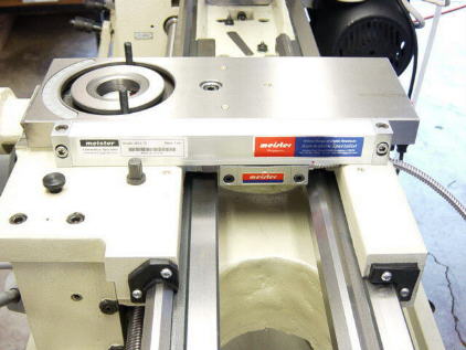
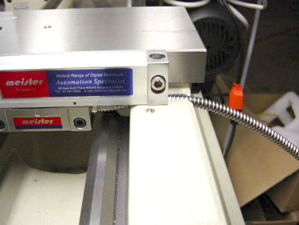
X axis scale mounted
The X axis is mounted flush against the compound slide
The instructions recommend a gap of 1.2mm to 1.5mm between the reading head and scale.
I used a feeler gauge shown above to set the gap. I then used a transfer punch
to mark the reading head attaching bolts.
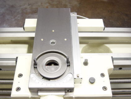
This shows how the notch allows the cable to pass under the scale.
I used a ball end mill to make the notch.
You will also notice a red dot on each end of each scale. There is also an arrow in the
center of the reading head. Make sure when mounting the reading head that the area
to be measured falls between the two red dots. The two scales provided allow more
than enough room for this.